Tube Amp Circuits A blog series explaining in detail how a single ended tube amplifier circuit works using the AE1 Kit circuit
Tube amps are by far the least efficient but I don t care They re simple circuits that get the job done with the fewest total components count the transistors inside a power opamp chip Abstract The design and construction of a single ended class A amplifier is presented By employing the use of tube technology and transformer coupling a musical sounding amplifier
Tube Amp Circuits
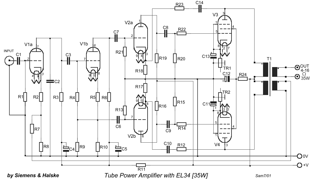
Tube Amp Circuits
http://www.hobby-circuits.com/files/508/tube-power-amplifier-with-el34-35w_orig.gif

Low Voltage Tube Amp Is Great For Beginners Valve Amplifier Amp
https://i.pinimg.com/originals/b8/3a/70/b83a701ad5a97a51978d15d2a238bcbb.jpg

807 Tube Audio Amplifier Schematic Cglasopa
https://cglasopa286.weebly.com/uploads/1/2/7/3/127357484/267354859.jpg
Building a Stereo Tube Amp Ever wanted to build a highly dangerous inefficient yet awesomely retro piece of electronics Well I have That s pretty much what a tube amp is Tubes and Circuits is a condensed engineering manual that teaches the theory and operation of vacuum tubes as well as circuit design In addition five projects are included that you can
The split load phase splitter circuit seldom is used standalone or as the output stage Most often nested between the input stage and the output stage the phase splitter circuit appears within tube based push pull power This free guide discusses all relevant aspects for an integrated push pull vacuum tube amplifier design including the power supply unit To clarify the various concepts I propose many practical examples using EL34 EL84
More picture related to Tube Amp Circuits

Tube Amp Schematics Tube Amp Information Tube Amp Projects Valve
https://i.pinimg.com/originals/e8/9b/0d/e89b0d6176559b111af7827a56648ba0.gif
Suppression Papa Tremblant Guitar Tube Amp Schematics Logique Remettre
https://el34world.com/projects/images/HoffmanStout18watt_No Switch_Schematic.GIF

Fender Deluxe Tube Amp Schematic Model 5C3 Electronic Circuit
https://i.pinimg.com/originals/7c/89/05/7c8905e27f30713d885a34593722efb2.gif
How preamp and power tubes interact with wattage and speaker ratings to yield the glorious tones of yesterday and today Famous tube amps from companies like Fender Marshall Vox and others have come to define Chronological list of our DIY vacuum tube Hi Fi audio projects Bruce Heran describes the design and construction of the Cranberry TwoC a stereo integrated all tube
Part of a blog series Tube Amplifier Circuits Explained You are likely familiar with a basic resistor a device that intentionally holds back current and is rated in Ohms I won t go Here we re going to take a look at the inner workings of standard amplifier circuits the tubes transformers resistors and capacitors that work together to create the
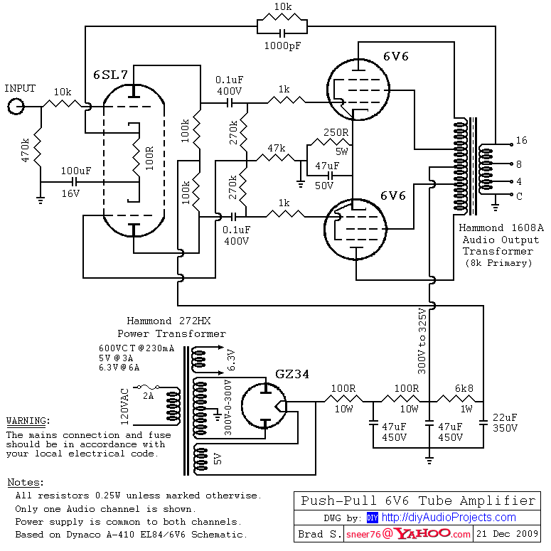
Hammond Transformers 6V6 Push Pull Tube Amplifier Circuit Diagram
https://1.bp.blogspot.com/-f40xe6QDlg0/TZUZSS1AimI/AAAAAAAADmw/LbKKjOO08rs/s1600/Hammond-Transformers-6V6-Push-Pull-Tube-Amplifier-Circuit.png
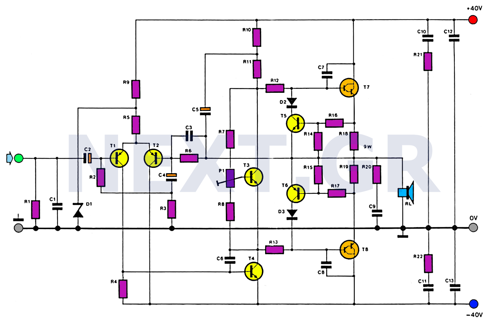
Simple 100W HiFi Audio Amplifier Circuit Diagram Electronic Circuits
https://2.bp.blogspot.com/-vgwwy_hmKXM/Wtx9rEWlmlI/AAAAAAAAKqY/VtokXh7oEUktGTYpY3TshU_7eEXqwEgzgCLcBGAs/s1600/Simple%2B100W%2BHiFi%2BAudio%2BAmplifier%2BCircuit%2BDiagram.png
https://www.analogethos.com/post/tube-a…
A blog series explaining in detail how a single ended tube amplifier circuit works using the AE1 Kit circuit

https://hackaday.com/2014/11/03/low-volta…
Tube amps are by far the least efficient but I don t care They re simple circuits that get the job done with the fewest total components count the transistors inside a power opamp chip
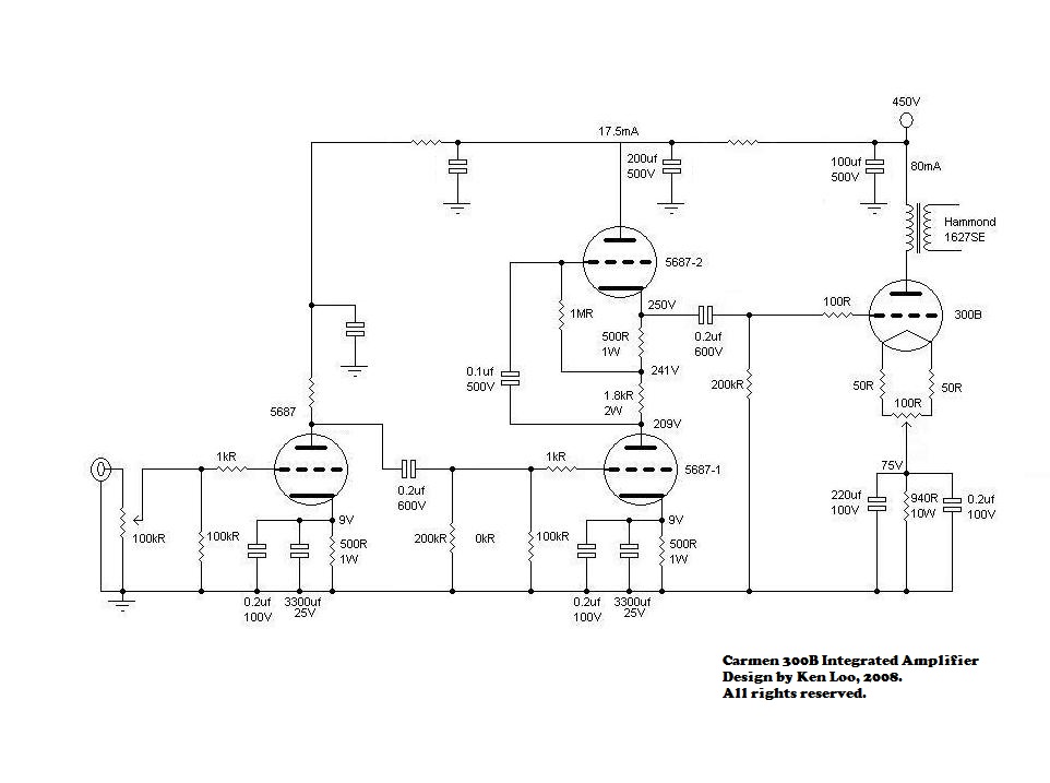
DIY 300B Amplifier

Hammond Transformers 6V6 Push Pull Tube Amplifier Circuit Diagram

Tube Lab Vacuum Tube Audio Amplifier Discrete Semiconductor Circuit

For The Op Amp Circuit In Fig Calculate The Output Voltage Vo

Diy Amplifier Electronic Circuit Design Power Amp Circuit Diagram

Top 10 Op Amp ICs Choosing The Right Amplifier For Your Circuit

Top 10 Op Amp ICs Choosing The Right Amplifier For Your Circuit
Lm741 Audio Amplifier Circuit Diagram

4558 Ic Preamp Circuit Diagram Diagram Board
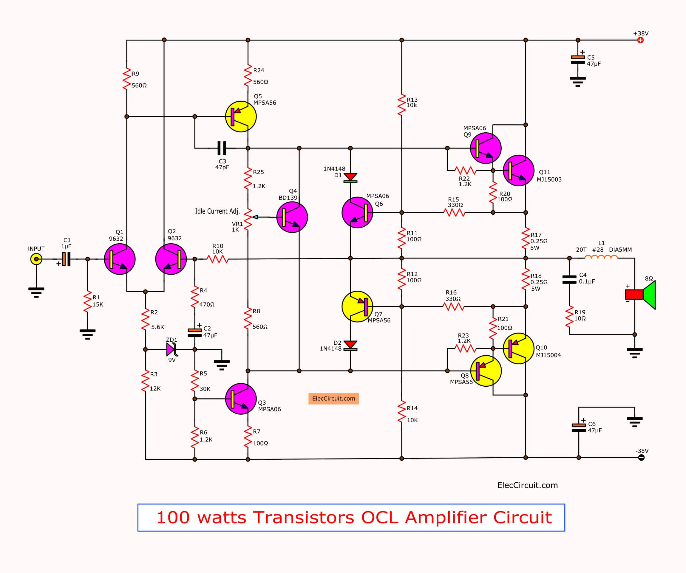
100w Amplifier Circuit With PCB
Tube Amp Circuits - The CCS is very useful circuit in tube amplifiers even though they are often made with solid state devices CCS is the short hand abbreviation for Constant Current Source or Constant Current
